The installation instructions of the Zip Hydroboil water heaters below are intended as a guideline only for the CORRECT installation of the HydroBoils. While every care has been taken to ensure that the information herein is correct, Franke Kitchen Systems (Pty) Ltd or Chilli-B will not be held responsible for installation conditions out of their control, unforeseen circumstances or conditions beyond the scope of this Installation Guide.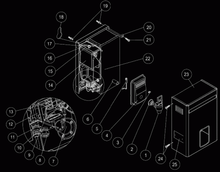
| 1.Outlet Tap | 10. Mains Cable Clamping Ferral | 19. Plastic Wall Mounting Inserts (Not Supplied) |
|---|---|---|
| 2. Tap Escutcheon | 11. “Conex” Water Inlet Fitting | 20. Mounting Screw Washer (Not supplied) |
| 3. Pilot light Lens | 12. Silicone Rubber Overflow Tube | 21. HydroBoil Mounting Screw (Not Supplied) |
| 4. Fascia Moulding | 13. Electrical Terminal Block | 22. Boiling Tank Assembly |
| 5. Pilot Light and Cable Assembly | 14. Cistern Tank Assembly | 23. Outer Case Assembly |
| 6. Boiling Tank Water Outlet Tube | 15. Spring Steel Lid Retain Clips | 24. Outer Case Fixing Screws (Both Sides) |
| 7. Heating Element | 16. Cistern Lid | 25. Rating and Serial Plate |
| 8. “Conex” Overflow Outlet Fitting | 17. Manual Reset Thermal Overload | |
| 9. Thermostat | 18. Key Hole Mounting Slots | |
Important Notes
Please read the entire procedure prior to commencing installation
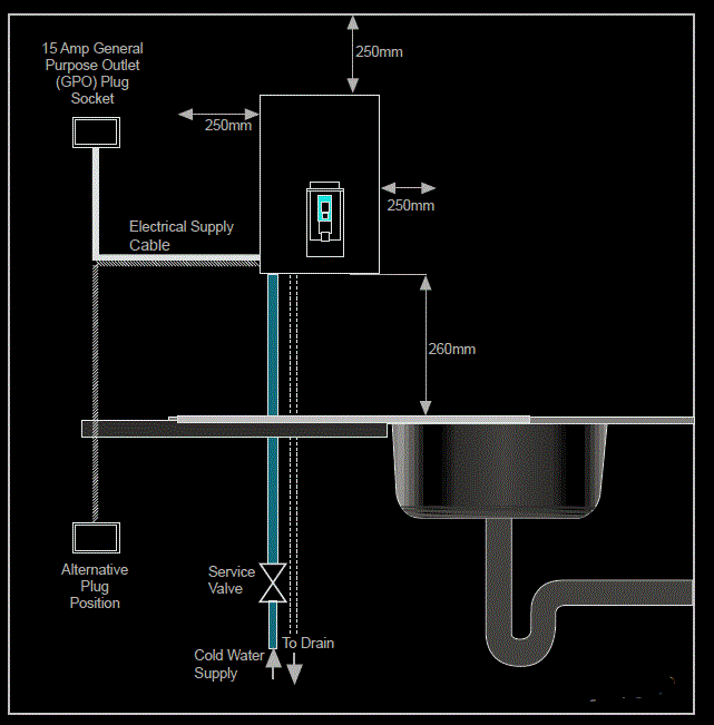
- Positioning the unit: Ensure the recommended ventilation measurements are in place, as per Figure 2 below. Do Not locate within easy reach of small children.
- Plumbing connections: Unions used when possible, for ease of removal and maintenance purposes. Water Connection should be made through an approved isolating cock (Strainer Valve and Stop Cock provided with the unit)
- Vent / Overflow: The Vent / Overflow Line should run from the unit to a safe drainage slope to avoid blockage and allow for easy venting – 1.5m maximum
- Flush pipes before connecting Franke HydroBoil to the water supply
- Check all plumbing for leaks before connecting power.
- Do Not connect electricity supply before the unit has been connected to the water supply and the water supply is turned on. NOTE WELL: It is essential that the Boiler Tank must contain a sufficient amount of water or else the element will be damaged when switched on. A sufficient amount of water is in the Tank only when water flows out of the Outlet Tap when opened.
- If the water pressure exceeds 400 kPa an approved 350 kPa, or less, pressure reducing valve must be installed in the cold water supply line.
- The minimum working pressure is 100 kPa.
- It is normal for the unit to discharge small amounts of steam and water from the Vent/ Overflow Outlet at the bottom of the unit or Extended Vent Pipe, particularly on the first filling at Installation or on the first filling after the unit has been drained of water for servicing or re-installation.
Step 1: Preparing the unit for installation
- Fix and secure Tap (No. 1) to the 15 mm copper extension in a vertical position with outlet draining point down, if not already in place. Use of Teflon thread tape is recommended.
- Remove cover screws and washers (No. 24). Depending on the model of Hydroboil, the Outer Case fixing screws are located at the top and bottom of the Outer Case or at either rear side of the Outer Case.
- Remove the Cover (No. 23).
Step 2: Installing the unit
- Position the unit on the wall. Using a spirit level, ensure the HydroBoil is correctly levelled from side to side by placing the spirit level along the top of the HydroBoil Chassis (No. 1a). Mark through the key holes (No. 18) onto the wall.
NB. Check the Minimum clearances and tap position above the counter as per Figure 2 are correct. Ideally the bottom of the HydroBoil should be 260 mm from any surface below the mounting position, to allow reasonable access for Jugs or large containers.
- Remove the HydroBoil from the wall and drill suitable holes in the wall. Ensure that the wall fixing bolts (hex head coach bolts are recommended) are of a size that are able to safely hold the weight of the unit, including the weight of the water-fill capacity as recommended and listed in the table below. Insert the wall plugs (No.19 – not supplied).
HydroBoil Model 2,5L 5,0L 7,5L 10L 15L 20L 25L Weight with Water (Kg) 11 14 18 23 31 46 88 Recommended Mounting Coach Bolt Gauge 2x No6 2x No6 2x No6 2x No6 2x No8 2x No8 2x No8 Wall Plug and Drill (mm) 8 8 8 8 10 10 10 
- Fit the washer (No.20 – not supplied) on to the Coach Bolt (No.21 – Not supplied). Place the top of the Key Hole Slots in the HydroBoil Chassis (No.1a) over the wall plugs and screw the coach bolt into the wall plug until it is tight against the HydroBoil Chassis.
- Recheck that the HydroBoil is level from side by side by using the spirit level, along the top edge of the Chassis, and if the HydroBoil has moved out of level, loosen the wall fixing bolts and adjust the level as necessary and retighten the bolts to lock the HydroBoil in the
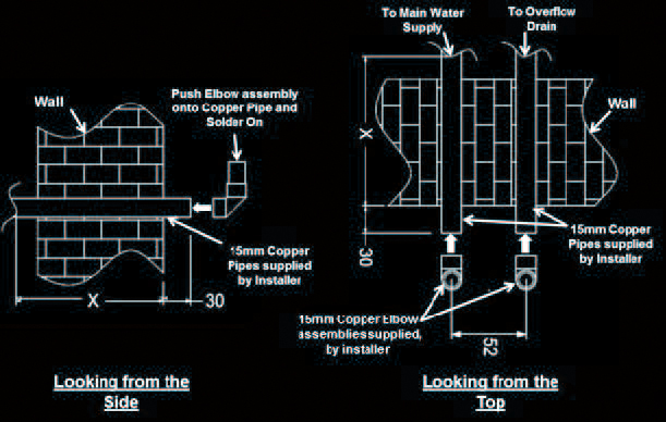
correct level position. - If hidden plumbing is required through the back of the HydroBoil (as per Figure 3a below) 2 off 20mm diameter holes must be drilled through the wall to allow the plumbing to be fitted into the HydroBoil. To obtain the correct position of the holes, mount the HydroBoil back
on the wall as points 3 and 4 above. Once the HydroBoil is mounted proceed as follows:-- Draw a pencil outline of the bottom and two sides of the cut out in the Chassis where the Water Inlet and Outlets are situated (bottom left corner of the HydroBoil)
- Remove the HydroBoil from its mountings.
- Draw a line parallel to the bottom marking of the cut out 5,0mm above it.
- Draw a line parallel to the left side line of the cut out 26,0mm to the right.
- Draw a line parallel to the right side line of the cut out 26,0mm to the left.
- Drill the two 20mm holes with their centres where the lines in c. d. and e. above intersect.
- Make the 2 off copper fittings with 15mm copper solder joint female elbows and 30mm long 15mm copper pipes. As below.
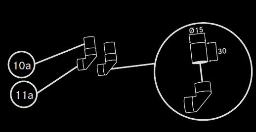
- NOTE: “Conex” copper to female iron elbows can be used but this is NOT recommended as it requires disassembly of some internal components of the HydroBoil, which may void the Warranty and, or, Guarantee if incorrectly reassembled.
- Fit the external 15mm Copper Water Inlet and Overflow Pipes through the 20mm diameter holes in the wall and cut to the appropriate length (X) for the wall thickness and connection to the plumbing on the outside of the wall and allow 30mm of copper tube to project out from the wall on the side where the HydroBoil is fitted, then solder the above copper elbow assembly to the end of each pipe with the elbow facing upward (90 degrees to the floor).
- Flush the plumbing to ensure that no solids of flux is inside the pipes.
- Lift the HydroBoil up until the copper elbow fitting are inside the HydroBoil Chassis and are directly under the “Conex” compression Water Inlet (No. 5a) and Overflow (No 7a) Fittings mounted inside the HydroBoils. Make sure the“Conex” compression fittings nuts are loose. Move the HydroBoil downward and guide the two copper elbow assemblies into the “Conex” Fittings.
- Fit the wall mounting bolts and tighten fully, then tighten the “Conex” compression nuts until the fitting is water tight.
- For exposed internal bottom entry plumbing connections, mount the HydroBoil on its wall fixings and fit the external 15mm copper pipes (supplied by Installer) directly into the “Conex” compression fittings that are supplied fitted to the HydroBoil (No. 5a and 7a) ONLY
after the plumbing has been flushed to remove any solids or flux . As per Figure 3b below.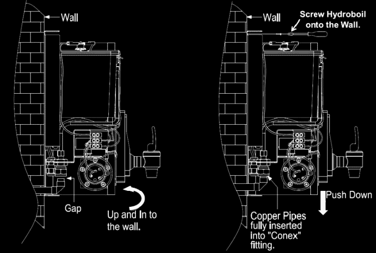
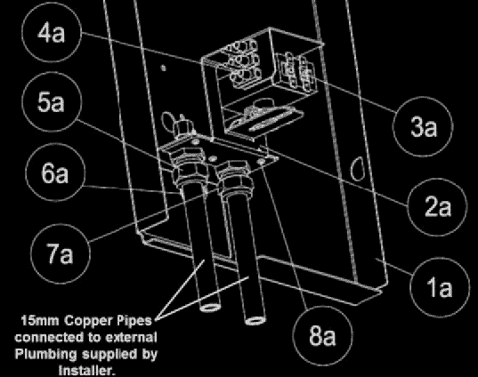
1a. Chassis 7a. Internal Brass Overflow fitting 2a. Thermostat - Inlet/Overflow Locking Bracket 8a. Thermostat bracket Fixing Screws 3a. Thermostat 9a. Conex Lock Nuts (Supplied) 4a. Electrical Terminal Block 10a. 15mm Copper Tube (Not Supplied) 5a. Internal Brass Water Inlet Fitting 11a. 15mm Solder Joint Copper Elbow (Not supplied) 6a. Cable Clamp/Ferrule - After completing the above, turn the water supply on and check for leaks. Re-tighten the “Conex” compression fittings in the HydroBoil if necessary.
- DO NOT PLUG THE HYDROBOIL INTO THE ELECTRICAL SUPPLY AT THIS POINT.
- Allow the water to flow until a constant stream of water flows out of the HydroBoil Outlet Tap. (No. 1), that may take up to 15 – 20 minutes depending on the HydroBoil model. This will ensure that the Heating Element is covered with water to prevent damage to the Heating Element when the electrical supply is connected and turned ON. Keep the water supply ON and close the HydroBoil Outlet Tap.
- Plug the Electrical Supply Cable Plug into the Electrical Wall Socket and turn the socket switch to ON. Check to see if the red Power ON Pilot Light (No. 5) on the Facia Moulding (No. 4) is illuminated. If the Pilot Light is not illuminated, recheck to see if the Electrical Cable Supply Plug is correctly inserted into the Electrical Wall Socket and the Wall Socket Switch is in the ON position. If this is all correct and the Pilot Light is still not illuminated proceed to the “TROUBLE SHOOTING GUIDE”.
- If the Pilot Light is illuminated and there is no sign of the water heating after 10 minutes proceed to the “TROUBLE SHOOTING GUIDE”.
- If the water starts heating and there are no water leaks, turn OFF the Electrical Wall Socket and unplug the HydroBoil’s Electrical Supply Cable from the Electrical Wall Socket, and refit the HydroBoil Outer Casing (No. 23) ensuring that all four Outer Casing fixing screws (No. 24) are fitted and fully tightened.
- Plug the HydroBoil Electrical Supply Cable Plug back into the Electrical Wall Socket and turn the Wall Socket to the ON position, recheck that the red Pilot Light is illuminated.
- As the HydroBoil is filling with water, to its maximum rated capacity, the internal factory set Thermostat should switch the Heating Element OFF and ON. If the water continues to boil constantly for more than 1 minute, normally identified by the “bubbling” noise associated with a boiling kitchen kettle and excessive steam coming out of the Overflow Pipe, turn the Electrical Wall Socket switch to the OFF position, unplug the Electrical Supply Cable to the HydroBoil, remove the HydroBoil Out Casing (No. 23) and proceed to the “TROUBLE SHOOTING GUIDE”.
- If the HydroBoil is functioning correctly, complete the Warranty Card ensuring that the Date of Installation and the HydroBoil’s unique Serial Number are correctly recorded on the Warranty Card and post back to Franke Kitchen Systems (Pty) Ltd.
- The installation is now complete.


2 Comments
Hi I need help of installation of 5lt hydro boiler….how much do you put one can I have price
Hi Mpho, once you purchased the water boiler you need to contact a plumber in your area to do the installation. You might also need an electrician if you don’t have a power supply close by. Prices are available online by following the links to Hydroboils and Kwikboils.